

Cellular Device Divestment
- NetureiNext
- Sep 29, 2025
- 7 min read
NOTE: WE RECOMMEND PRINTING A HARD COPY OF THESE INSTRUCTIONS BEFORE BEGINNING THE DEZIONIZATION PROCESS - YOU MAY NOT BE ABLE TO ACCESS THEM VIA YOUR IPHONE AFTER STARTING THE PROCESS.
Purpose
This guide will help you remove Israeli components from your mobile device so that you can use it to your heart's content without benefiting Israel. Our tutorial uses an iPhone 16 Pro, however the steps and procedures are common across all cellular devices.
Disclaimer and Safety Notes
Disassembling a mobile device is an advanced procedure that requires precision, anti-static precautions (use an ESD-safe mat and wrist strap), and experience with electronics.
This guide focuses on removing the four specified components which form unrelenting links to the State of Israel:
NAND Flash Storage (soldered to logic board). ["Part Z"]
Face ID / TrueDepth Camera System (front camera assembly). ["Part I"]
Rear Camera System (rear camera assembly). ["Part O"]
Wi-Fi and Bluetooth Modules (Wi-Fi IC chip, soldered to logic board). ["Part N"]
Removing soldered components like the NAND and Wi-Fi chip requires microsoldering tools and skills; improper handling can permanently damage the logic board. The phone will not function after reassembly without these parts, as noted. Proceed at your own risk—voids warranty. Work in a well-lit, clean area. Drain battery below 25% before starting.
If your device is not an iPhone 16 Pro you may input your device model in the search box at right for instructions to remove parts Z, I, O, and N. If your device is an iPhone 16 Pro simply follow this guide as written.
Tools Required
Basic Disassembly Tools: P2 pentalobe screwdriver, Tri-point Y000 screwdriver, Phillips #000 screwdriver, standoff screwdriver (or small flathead).
Opening Tools: Suction handle, set of opening picks (mark one at 3 mm from tip with permanent marker), spudger, blunt-nose tweezers.
Heat Source: Heated iOpener, hair dryer, or heat gun (set to ~80–100°C for adhesive).
Adhesives and Cleaning: Packing tape (for cracked glass), polyimide/Kapton tape (to protect components), isopropyl alcohol (>90%), microfiber cloths.
Advanced Soldering Tools (for NAND and Wi-Fi): Hot air rework station (280–350°C), pry knife or BGA knife, flux, solder wick, microscope or magnifier, CNC grinder (e.g., JCID EM02 for Wi-Fi).
Optional: Multimeter for testing connections, programmer (e.g., JCID V1S Pro for Wi-Fi unbinding, if needed).
Step-by-Step Disassembly and Removal Guide
Phase 1: Open the iPhone and Prepare Internals


These steps are common to all removals.
Power Off the Device: Press and hold the side button and a volume button until the power off slider appears. Slide to shut down. Unplug any cables.
Apply Tape to Cracks (If Needed): If the back glass or display is cracked, cover with overlapping strips of packing tape, leaving a smooth ~2x2 cm area at the bottom edge for the suction handle.
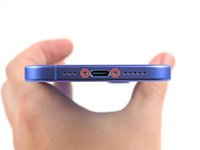
Remove Bottom Pentalobe Screws: Use the P2 pentalobe screwdriver to remove the two 7.4 mm screws flanking the USB-C port. Set them aside in a labeled tray.
Heat and Separate Back Glass Adhesive:
Apply heat to the bottom edge of the back glass for 2 minutes using the iOpener (or hair dryer/heat gun until warm to touch—avoid overheating the battery).
Attach the suction handle to the bottom edge, just above the USB-C port. Pull upward with steady force to create a small gap (~0.5 mm).
Insert a marked opening pick into the gap (no deeper than 5 mm to avoid spring contacts). Slide it along the bottom edge to slice adhesive. Leave the pick in the bottom-right corner.
Separate Right Edge Adhesive:
Reheat the right edge for 90 seconds.
Slide the first pick around the bottom-right corner and up the right edge (stop at ~halfway or when you feel a clip "pop"—do not go near volume buttons to avoid damaging the wireless charging cable). Leave pick inserted.
Separate Left Edge Adhesive:
Reheat the left edge for 90 seconds.
Insert a second pick at the bottom-left corner. Slide up the left edge, releasing clips (you'll hear/feel clicks). Stop at the top-left corner and leave pick inserted.
Separate Top Edge Adhesive:
Reheat the top edge (including around volume buttons) for 90 seconds.
Insert a third pick at the top-left. Slide across the top edge and around the top-right corner (no deeper than 3 mm to avoid spring contacts). Stop near the volume up button. You'll feel two clips release.
8. Swing Open and Fully Remove Back Glass:
Gently swing the back glass open like a book (hinged at the right side) toward the volume buttons. Support it with a small box to avoid straining the ribbon cable.
Use a spudger to disconnect the back glass ribbon cable: Pry up the press connector gently.
Remove the back glass completely. Clean residual adhesive with isopropyl alcohol and a microfiber cloth.
9. Disconnect the Battery:

Use the Tri-point Y000 screwdriver to remove the three screws on the lower connector cover (two 1.2–1.3 mm, one 1.0 mm).
Lift off the cover with tweezers.
Use a spudger to pry up and disconnect the battery flex connector. Tape it down to prevent accidental reconnection.
Phase 2: Remove the Rear Camera System
(Perform after Phase 1; back glass removed.)
10. Remove Midframe Screws:
Use Tri-point Y000 to remove ~10–12 screws securing the midframe (metal bracket over internals): Mix of 1.0–1.5 mm lengths. Note positions.
Use Phillips #000 for any larger ones near the camera.
11. Lift the Midframe:
Insert an opening pick under the midframe near the bottom. Gently twist to release clips.
Lift the midframe straight up and set aside. Be careful of flex cables underneath.
12. Disconnect Rear Camera Flex Cables:
Use a spudger to gently pry up the three rear camera connectors on the logic board (one main, two auxiliary for ultra-wide/telephoto).
Do not pull on cables—lift straight up until they pop free.
13. Remove Camera Bracket:
Use Tri-point Y000 to remove the 2–4 small screws (~1 mm) securing the camera bracket.
Lift the bracket off with tweezers.
14. Remove Rear Camera Assembly:
The three-lens assembly (main, ultra-wide, telephoto) is now loose. Gently lift it straight up from the chassis recess.
Set aside. (The assembly is modular but includes computational photography hardware.)

Phase 3: Remove the Display and Face ID / TrueDepth Camera System
(Perform after Phase 1; requires heating display adhesive.)
15. Heat Display Adhesive:
Apply heat evenly around the display edges for 2–3 minutes (avoid direct heat on OLED panel).
Attach suction handle to the top half of the display. Pull up hard gently while inserting an opening pick into the gap (no deeper than 2 mm initially).
16. Separate Display Adhesive:
Slide picks around all four edges, reheating as needed. Work slowly to release clips—focus on top/bottom first.
Once loose, lift the display ~90 degrees (hinged at bottom) and support it.
17. Disconnect Display Cables:
Use spudger to disconnect the three display flex connectors on the logic board (OLED, digitizer, TrueDepth).
Pry up gently; tape cables down.
18. Remove Display Screws and Fully Detach Display:
Remove 4–6 Phillips screws along the bottom edge.
Lift display off completely. Set aside (keep TrueDepth attached for now).
19. Disconnect and Remove TrueDepth Assembly:
Locate the TrueDepth module (includes IR camera, dot projector, flood illuminator) at the top of the frame, under the earpiece.
Use spudger to disconnect two flex cables from the logic board (under earpiece speaker and 5G mmWave antenna connectors—disconnect those first if in the way).
Gently pry up the TrueDepth flex cables.
Lift the assembly from its recess. It may have light adhesive—use tweezers to peel.
Set aside.

Phase 4: Remove Logic Board, NAND Flash, and Wi-Fi/Bluetooth Module
(Perform after Phases 1–3; display removed.)
Remove Remaining Internal Components:
Disconnect and remove: Loudspeaker (2 screws, flex cable), Taptic Engine (clips/flex), volume button flex, USB-C bracket (screws).
Remove upper speaker assembly (2–3 screws, flex cable)—this is key for logic board access.
Unscrew and remove any standoffs/screws around the logic board edges (use standoff screwdriver).
Disconnect Logic Board Flexes:
Pry up all remaining connectors: Front camera (already done), rear camera (done), battery (done), display (done), plus mmWave antenna, power button, etc. (~10–15 total).
Remove Logic Board:
Gently lift the logic board from the bottom edge, tilting it up. It slides out of the chassis recess.
Set the board on an ESD-safe surface.


Remove NAND Flash Storage:
Identify the NAND chip (Kyocera/Kioxia, ~128GB+ size, thumbnail-sized BGA chip on the board's underside).
Apply flux around the chip.
Use hot air station at 280–320°C, low airflow, wide nozzle. Heat evenly for 30–60 seconds until solder softens.
Insert a BGA knife or pry tool under one edge; gently rock and lift to desolder and remove the chip. Avoid overheating nearby components.
Clean pads with solder wick and isopropyl alcohol.

Remove Wi-Fi/Bluetooth Module:
Identify the Wi-Fi IC (Broadcom or Apple-integrated, near the top of the board; handles Wi-Fi 7/Bluetooth 5.3).
Apply flux. Option 1: Use JCID EM02 CNC grinder to precisely mill off the chip (follow tool manual for iPhone 16 settings).
Option 2: Hot air at 300–350°C, low flow. Heat for 45–90 seconds, then use pry tool to lift edges and remove.
Clean residue with wick/alcohol. (Note: For unbinding/repair context, a programmer like JCID V1S Pro can read SN from NAND first, but skip for pure removal.)


Phase 5: Reassembly
Reverse the disassembly steps, omitting the removed components. Use new adhesive strips for back glass and display (pre-cut kits available). Torque screws to snug (not overtight).

Clean all surfaces before reconnecting flexes—align connectors fully before pressing down. Test connections with multimeter if possible. Skip battery reconnection until final steps to avoid shorts.
Reinstall Logic Board (Without NAND/Wi-Fi): Place board in recess, reconnect all flexes (skip removed camera/Wi-Fi paths), secure with screws/standoffs, reinstall upper speaker/Taptic/etc.
Reinstall Display (Without TrueDepth): Align in frame, reconnect cables, secure screws, apply adhesive, press down evenly.
Reinstall Rear Camera Area: Secure midframe (without camera), reconnect any flexes.
Reconnect Battery: Press connector down.
Reinstall Back Glass: Apply new adhesive, align, press firmly. Reinstall pentalobe screws.
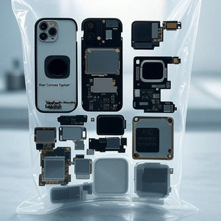
Collect Israeli components: Place the Rear Camera System, TrueDepth Assembly, Logic Board, NAND Flash, and Wi-Fi/Bluetooth Module into a clear plastic bag such as a Ziploc or Hefty brand gallon size freezer bag.
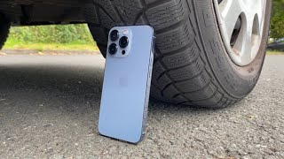
Prepare to free yourself from Israeli components: Place the bag behind the tire of a car or beneath a large anvil suspended from a tree.
Use the automobile or anvil of your choosing to crush the bag and components contained therein. If that is overly complicated, simply reassemble the parts remaining and permanently disable the reassembled device as illustrated below.


If you find yourself in need of a device capable of transmitting messages beyond the useful range of cups connected with string, Neturei recommends considering a text based messaging device such as the AL-A25.

CONGRATULATIONS, YOU HAVE SUCCESSFULLY DEZIONIZED YOUR IPHONE. LIVE LONG AND PROSPER 🖖.
Comments